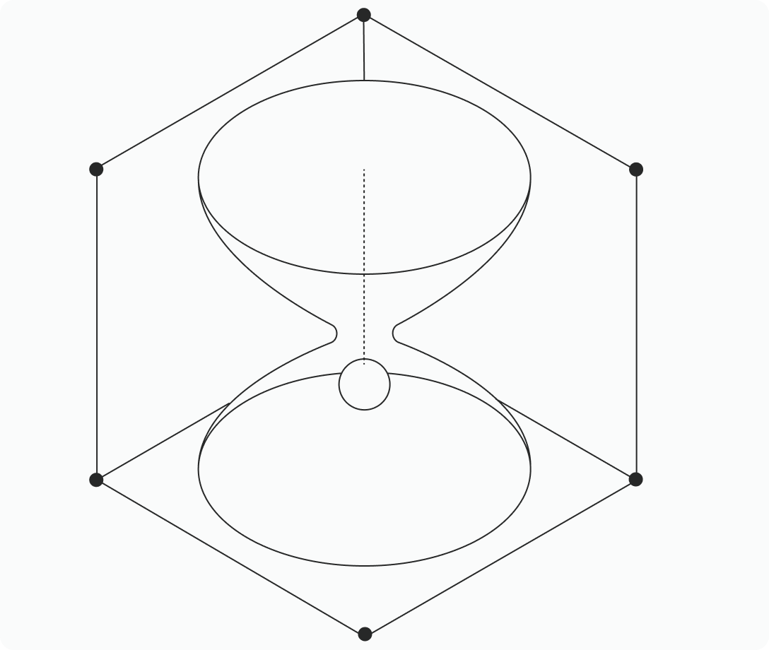
Comsol boundary system. a vector over time, with discrete boundary fluxes.
Comsol boundary system The second tangent direction (t o) is the cross product between normal vector (n) and the first tangent direction (t 1). In the mathematical treatment of partial differential equations, you will encounter boundary conditions of the Dirichlet, Neumann, and Robintypes. model. What are the default boundary conditions on the axis of symmetry (I see in this case the axis of symmetry is not included on the domain). You can use one of the following approaches to solve this differential equation using COMSOL: 1. The simplest option is to use a Flux/Source boundary condition, as shown in the figure below. 5a and older, you must activate one boundary at at time with the mouse. When using Weak constraints, the Lagrange multiplier variable will be constrained on the excluded entities, which effectively removes the constraint. BOUNDARY CONDITIONS. The periodic boundary condition typically implements standard periodicity so that u (x 0) = u (x 1) (that is, the value of the solution is the same on the periodic boundaries). In the COMSOL Multiphysics ® software, you can use coordinate-based selections, which include the Ball Selection, Box Selection, and Cylinder To add a periodic boundary condition, in the Model Builder, right-click a physics interface node and select Periodic Condition. The Global Equations node in COMSOL Multiphysics supports such IVPs described with an equation in the following form: , including initial values for u and its derivatives. To reduce the influence of the exterior boundary conditions to say O(10^{-2}), we would have to locate the exterior boundaries of the computational domain a distance of order of 100 obstacle sizes away in 2D and 10 obstacle sizes away in 3D. Hence, the typical mapping of interest here is from the source boundary to the destination boundary, however, it is possible to map quantities in the opposite direction as The boundary element method (BEM) is included in the Acoustics Module as a physics interface. So: All I want to do is calculate a surface vector somewhere on the boundary surface of a 3D geometry that is not given by a parameter but directly by its coordinates. I know you are not from Comsol, but I consider you Comsol HERO. An "open boundary" allow two-way flow with free pressure and velocity definition. It seems to work ok when i apply a velocity in a direction in the global system, or a boundary load in both the boundary and global system but it won't work for a velocity. The COMSOL Multiphysics UI showing the Model Builder with the Flux/Source boundary condition selected, the corresponding settings, and the Graphics window showing the rectangular plate. Apr 28, 2021 · The boundary system can have either fixed directions, or directions that follow the deformation. 0 0 Replies . I’ve noticed that even if a boundary condition is not prescribed on the axis of symmetry, comsol doesn’t set zero flux on the axis. Tabulated Environmental Thermal Conditions About the Thin Elastic Layer Boundary Condition. That would be a on the boundary surface. All vectors are expressed in the selected coordinate system. It is assumed that the boundaries are parallel to each other. Then enter values or So you usually have to create a new boundary condition if you want something other than continuity there. The combination of COMSOL ® products required to model your application depends on several factors and may include boundary conditions, material properties, physics interfaces, and part libraries. The boundary element method (BEM) is included in the Acoustics Module as a physics interface. t1 is selected Initial-value problems (IVPs), where the solution u and its derivatives (often with respect to time) are specified in one point (in time) so that u (0) and are known, so the system is assumed to start at a fixed initial point. Heat Transfer Module Updates. So you usually have to create a new boundary condition if you want something other than continuity there. They are small unless the element has an extremely high ratio between thickness and radius of curvature, in which case the errors from using shell theory are large anyway. This, of course, assumes that the analysis is Feb 20, 2012 · Hi all, I am using the laminar flow module in COMSOL 4. This, of course, assumes that the analysis is geometrically nonlinear, so that there is This local membrane surface coordinate system is defined by the boundary coordinate system (t l, t 2, n). Prescribe the displacement in the normal direction with something like -genext1(nx*u+ny*v+nz*w). 2), a specific physics interface called Piezoresistivity, Boundary Currents was added to the Model Builder. The entries in this section should be given as vector components in where P i is the fist Piola-Kirchoff stress tensor, T i is the nominal traction, and N i is the normal vector in the material frame for the respective sides of the interface. I have neither not a full view yet, but the default "Boundary system SYS1" is the boundary system defined on any surface = boundary of your system. This coordinate system is always right-oriented. Tim Brox . Too many inconsistencies and somehow vague in some parts. So the rainfall infiltration boundary conditions involve switching between Dirichlet and Neumann boundary conditions. Boundary System 2 (sys2) 1 In the Definitions toolbar, click Coordinate Systems and choose Boundary System. In both systems the Stokes (creeping flow) equations are solved. Then add a Prescribed Displacement in a local system (e. The schematic on the left corresponds to the 2D axisymmetric geometry implemented in COMSOL Multiphysics. e. This is determined by the Frame setting in the Boundary System node. Mass flow is set in the Figure 5 shows the mass flow rate through the tube, as a function of the applied pressure. Is the ball selection option possible? This seems to only select current boundaries not create a new circular boundary. In the above expression, the Macaulay The Rigid Connector is a boundary condition for modeling rigid regions and kinematic constraints such as prescribed rigid rotations. The physics interface controls the frame deformation if the Deformed mesh check box in the physics interface node Note that calling it a "continuous" boundary condition is not quite the right terminology here. To reduce the influence of the exterior boundary conditions to say O(10^{-2}), we would have to locate the exterior boundaries of the The default Boundary layer stretching factor is 1. Posted: 8 Hence, the pressure coefficient diminishes as d/R in 2D and as (d/r)^2 in 3D. 0a In order to mesh the structure I intend to mesh a 2D boundary first using the 'Free mesher' and use the 'Swept mesher' to extend the mesh to 3D. A Boundary System is a local base vector system on 2D boundaries (t, n) and on 3D boundaries (t 1, t 2, n). In the model library, there is a similar sensor example where the piezoresistive material is applied to a boundary. Therefore I'm using Navier-Stokes application and moving mesh application. In addition to that, the Reverse Normal direction option is selected in the Boundary System node in order to point the normal vector Also, d is the out-of-plane geometry extension (out-of-plane thickness for 2D systems, or cross-sectional area for a 1D or 1D axisymmetric system). w. This, of course, assumes that the analysis is The following example demonstrates a number of possible boundary condition combinations for a stationary system with two dependent variables u 1 and u 2 and two constraints when reaction In these tutorials you will learn how to set up a boundary layer mesh and modify the settings for an automatically created boundary layer mesh. since the problem is vibro- Acoustics, i would like to know about the ability of COMSOL to do that. I have tried different methods to only restric movement in the x direction, i. Should I use 'Boundary similarity' to couple the velocity variable on the bottom edge to the top? Do you know what the resultant boundary loads in comsol solid mechanics are in the x and y directions in a two-dimensional model? I want to know their positive direction. the force of the pull while allowing free movment in the Y and Z. To determine the right combination of products for your modeling needs, review the Specification Chart and make Then add a Prescribed Displacement in a local system (e. a Boundary system) on the other boundary. To determine the right combination of products for your modeling needs, review the Specification Chart and make This is to ensure current continuity across this boundary. Parcourez les fils de discussion et partagez vos idées avec la communauté COMSOL. To determine the right combination of products for your modeling needs, review the Specification Chart and make Hello, I am quite new to COMSOL Multiphysics, currently modelling a multiphase flow using level set. Shell Properties This section is only present in the in the Layered Shell interface, where it is described in the documentation for the Boundary Load node. t1 and t2 are the tangents of your 2D boundary. As boundary conditions: on heart surface I use dirichlet boundary condition, and on torso surface I use neumann boundary condition. Select a Friction model — Coulomb, Exponential dynamic Coulomb , or User defined . Boundary Load. I got stuck at this point, haven't found good way to define the boundary conditions. t1y. 2a. Finally, the equivalent lumped system is simulated with a single resistor carrying the equivalent thermal resistance of the ceramic layers. Any ideas? Thanks!! To add a periodic boundary condition, in the Model Builder, right-click a physics interface node and select Periodic Condition. Then enter values or expressions for the components in the matrix based on the selection and the space dimension. Please login with a confirmed email address before reporting spam. For some reason I cannot apply boundary conditions to the middle boundary of the rectangle for the NS app. The Plane Stress Constitutive Relationship For an introduction to plane stress and other 2D structural mechanics formulations, see our blog post on the difference between plane stress and plane strain . For cylindrical and spherical waves, COMSOL Multiphysics uses the corresponding 2nd-order expressions from Bayliss, Gunzburger, and Turkel (). Thank you, Ivar. Enclosing the system within a convex set of Magnetic Insulation boundary conditions represents an approximation of free space. The vacuum pump boundary condition is used for the pumps and the outgassing wall boundary condition is used for the wafer surface. The Selection List window, displaying the index numbers for all the domains (left) and boundaries (right) of a model geometry. Posted Oct 2, 2012, 7:56 p. The Molecular Flow Module offers a variety of boundary conditions that can be assigned to a model. It is suited for all frequency-domain simulations with harmonic variations of the pressure field. But when I plot the values at boundary using cross-section plot parameters dialogue box or export the data at the boundary, the boundary values range from 0. For Pressure , it can represent a pressure or another external pressure. I want to integrate Heat Transfer between the 2 fluids, however, when I apply the temperature boundary condition to the initial Initial-value problems (IVPs), where the solution u and its derivatives (often with respect to time) are specified in one point (in time) so that u (0) and are known, so the system is assumed to start at a fixed initial point. 01 m). These selections can then be utilized for all of the steps in creating your simulation, such as specifying materials and applying boundary conditions. The direction of the incident light is defined by two angles, \alpha_1 and \alpha_2 ; and two vectors, \bf{n} , the outward pointing normal of the modeling space and \bf{a_1} , a vector in the plane of incidence. Select the Load type — Force per unit area, Pressure, Total force, Resultant, or for 2D components, Force per unit length. Now, a predefined multiphysics coupling approach is used, improving the flexibility and design options for I am trying to build a heat exchanger in comsol with fluid flowing like attached file. The geometry for the vacuum system is imported, but the wafer and its carrier are generated within COMSOL Multiphysics so that the angle to the beam line can be easily parameterized. I need to solve a system of two coupled second order elliptic PDEs for quantities u and v; there are no boundary conditions imposed on v, but both u and the normal component of the gradient of u are specified on the boundary. While it is clear that constant/floating potential BC corresponds to a conductor surface, I can't figure out a similar correspondence for the "opposite" Zero Charge BC. The constraint contains derivatives of the 2 variables. The Thin Layer boundary condition can model a thin air gap between parts. Select a Load type — Force per unit area (the default), Pressure, Total force, or for 2D components, Force per unit length. But I don't understand why. In the Model Builder, under Component, find the physics-related heading (e. Mathematically, the boundary condition is (4) and (5) In COMSOL Multiphysics, the only input required is a contact angle, θ. Almost all the posts in Comsol that at least I visit, are answered by you. The periodic boundary condition typically implements standard periodicity so that u (x 0) = u (x 1) (that is, the Dear all, my system is made of two subdomains, the external rectangle (with velocity inlet and pressure outlet conditions and a boundary stress on the interface with the cylinder) and the inner cylinder (velocity inlet u2=u and v2=v and pressure fixed in the rear stagnation point). To determine the right combination of products for your modeling needs, review the Specification Chart and make Apr 29, 2021 · The boundary system can have either fixed directions, or directions that follow the deformation. Send Private Message Flag post as spam. 5 includes a new Lumped Thermal System interface, multiple spectral bands for the Radiation in Participating Media and Radiation The problem with this method is that COMSOL treats these as two seperate simulations and I cannot postplot my results continuously from 0 thru to 4! Well I havnt tried it out, but I would have studied the "Equation System - Boundary Settings - Variables" - It also provides a natural way to specify boundary conditions in terms of the heat flux. In a geometrically linear analysis, the nonlinear terms (products between u, a, and their derivatives) disappear. When the connection is used for an edge which is shared between boundaries, the coordinate system can be ambiguous. This would match realistically with my physical K. See the Moving Frame Domain Condition section for details. Actually that trend is similar to the results of the PDE inside the domain. The pressure is positive when directed toward the solid. There are two fundamental ways to specify what is happening at a boundary, and two corresponding fundamental boundary condition types: Flux conditions specify how the Generally Comsol offers two coordinate system for vector functions: 1. Impose similarly the telegrapher’s equation 2pi ri·dV/dr = µl·dI/dt+R#·I at the inner boundary via Physics - Equation system - Boundary settings (Ctrl+F8) put: The viscous and thermal boundary layers are clearly visible. • For Force per unit area, the body load as force To add a periodic boundary condition, in the Model Builder, right-click a physics interface node and select Periodic Condition. 3 means that the thickness increases by 30% from one layer to the next. 2. 8 to 64. For Total force, COMSOL Multiphysics then divides the total force by the area of the surfaces where the load is active. The plotted boundary values are changing with time also. This boundary condition has both elastic and damping properties and acts between two parts to model a thin elastic layer with specified stiffness and damping properties. Physics interfaces that support infinite elements or perfectly matched layers when you have a doubt like that, turn on the "equation settings and the equations view" (under "options", or top border icon of physics tree) and check the underlying equations of COMSOL, in both the Equation tab, and the equation view node. To determine the right combination of products for your modeling needs, review the Specification Chart and make . rho) but I can't. Is there any way i can identify that part? 1 Reply Last Post May 22, 2017, 2:07 p. One easy method of doing this is to use the built-in physics interfaces for mass transport, as you would simply choose the 2D Axisymmetric option when adding the The combination of COMSOL ® products required to model your application depends on several factors and may include boundary conditions, material properties, physics interfaces, and part libraries. Prescribed Displacement. A rigid connector can connect an arbitrary combination of boundaries, edges, and points which all will move together as Boundary Conditions. Boundary systems (Local) So you can use the second one which gives you tangential and normal Learn how to implement boundary conditions and constraints for variational problems in COMSOL Multiphysics®. After going through the comsol discussion forum I found that it must be a case of BCs. Returned solution is not converged. We will also show how to implement these boundary conditions and constraints in the COMSOL® software using the same variational problem from Part 1: (the soap film) — and just as much math. For mechanical contact, most variables and equations are formulated on the destination boundary. To specify the thickness of the first element layer — the layer adjacent to the corresponding boundary — choose an My main consideration for this after trying various things is the issue of the constraint boundary that is placed in junction with the displacement boundary. Beware however that the rotating motion between two cylindrical surfaces may easily become more constrained than you intend, just because of small The second and third equations are the boundary conditions, which must hold on ∂Ω. A contact angle is imposed on the boundaries. EDT Computational Fluid Dynamics (CFD) Version 4. What I need to do is to set the boundary conditions on the left, with fluid flowing from the bottom to the top. If at an arbritrary timeintervall "delta_t_i", the boundary flux provided is larger than the porous media can physically sustain* water flow, convergence problems in COMSOL simulations arise. Part 2 of a math-focused blog series. 75 for a test and let u0 scan from -1 to 1 you get a solution per u0, as well as an unique solution on the domain 2 because you have the zero flux on the right Hello everyone! Please help me understand the physical meaning of the Zero Charge boundary condition (BC) in electrostatics. This adds a node with the same name, as well as a default Boundary Layer Properties node and at the same time inserts boundary layer elements for the selected boundaries, with the meshed domains adjacent to the selected Le forum de discussion COMSOL couvre une grande variété de sujets de simulation. Dmitry The combination of COMSOL ® products required to model your application depends on several factors and may include boundary conditions, material properties, physics interfaces, and part libraries. yes I know the boundary system tangential components but I am not using them, I am using the built in t1x, t1y and t1z which are defined by comsol as explained in the documents under 3D tangential variables, in my case they are different than sys. EDT. For Total force, COMSOL Multiphysics divides the total force by the area of the boundaries where the load is active. Set the electric potential of the electrode or specify a current condition that the potential of the electrode shall fulfill, and use subnodes to specify The normal vector on the surface is given by . Use the Electrode Surface node to model an electrochemical electrode-electrolyte interface between an electrolyte domain and an electrode boundary where the electrode is not included explicitly as a domain in the model geometry. The third equation is a general constraint, with a Dirichlet boundary condition as a special case. Since the Nitsche method is implemented as a distributed contribution If the physics interface controls the deformation of the material or the spatial frame, use the Moving Frame Boundary Condition node to specify the boundary conditions for domains with Free frame motion. a vector over time, with discrete boundary fluxes. coordSystem(). 海 林 . Written in general form: To add a periodic boundary condition, in the Model Builder, right-click a physics interface node and select Periodic Condition. • When This type of boundary condition is also called a Neumann boundary condition. The formulation is based on the Radiation boundary conditions are available for all types of studies. 4, If you still need help with COMSOL and have an on-subscription license, Now to understand how COMSOL isusing these and how they are related (Tinf is only linked to "h") take a look at the equations: Once you have selected 2D "htgh" BC's "Heat transfer" and the boundary of interest go to : Physics I knew that in v3. This method always gives a right-oriented orthonormal system, unless the tangent direction Apr 15, 2014 · The upper boundary is an atmospheric boundary condition, i. You can change the direction by reversing the sign before the numerical value Le forum de discussion COMSOL couvre une grande variété de sujets de simulation. The first axis of laminate coordinate system is aligned with the global x direction but with the normal direction is pointing inward. I wish you were the Author of the Comsol manual. 5 it was physics>equation system>boundary setting System matrix is zero. The default is Use face with lowest number. It just says "not applicable. System matrix is zero. Do you know how comsol can take a moving edge that does not know its real-time position as the coordinate system? thanks a lot. The 1,2,3 are the three coordinates in that order for a right hand cartesian projection, usually x,y,z or t1,t2,n (in 3D) where n is the normal (outwards = up). Select the boundary which should define the local system. By adding the Predeformation subnode, you can prescribe that the spring force is zero at a nonzero spring extension. Add a Boundary to Boundary node to connect two shell boundaries that are geometrically disjoint. The boundary condition between an isothermal domain and surrounding domains. The periodic boundary condition typically implements standard periodicity so that u (x 0) = u (x 1) (that is, the I have neither not a full view yet, but the default "Boundary system SYS1" is the boundary system defined on any surface = boundary of your system. EDT Fluid & Heat, Computational Fluid Dynamics (CFD) Version 5. For physics-controlled meshing a boundary layer mesh is automatically added for In COMSOL Multiphysics, Selections provides a tool to organize your model tree and solve such issues. whats the difference and relationship of boundary system and global coordinate system . Does anyone know why this is and if theres any way around it? I am using version 4. Muffler-like system with a Helmholtz resonator. r and sys2. In COMSOL Multiphysics®, you can use coordinate-based selections, which include the Ball, Box, and Cylinder selections, to create selections The combination of COMSOL ® products required to model your application depends on several factors and may include boundary conditions, material properties, physics interfaces, and part libraries. So, what is the default boundary condition Hi, I'm new to comsol and the answer maybe obvious to some of you, but here's my situation. The periodic boundary condition typically implements standard periodicity so that u (x 0) = u (x 1) (that is, the These selections can then be utilized for all of the steps in creating your simulation, such as specifying materials and applying boundary conditions. If you have a vector field given by , then the component of that field that is along the normal to the aforementioned surface is given by its scalar product with that surface normal vector, i. This interface, available as of version 5. Use it to apply loads and other boundary conditions in a normal or tangential direction on a boundary that is not aligned with the global Cartesian coordinate system. For instance if I have a box, the right hand side should displace parallel to 'y' axis due to some known force. Since there are many internal boundaries (around 200) selecting them With the Well boundary condition — new in COMSOL Multiphysics 5. Particular functionality may be common to several products. Oct 2, 2012 · Boundary condition coordinate system in 3D CFD model. Friction Parameters. For more information about the boundary conditions, see The General Form PDE. (Boundary Condition) "--Good luck Ivar Ayan Roy Choudhury. I hope I could explain my problem in a simple way. , . Combining conditions of different types on the same boundary is possible because of a new dependent variable μ, which is defined only on the boundary. The total mass in the system is computed by integrating the phase field variable over the domain: (6) This integrated quantity In the second approach, to avoid resolving the thin domains, the Lumped Thermal System physics interface is used and coupled to the remaining domains through boundary conditions. Hello everyone! Please help me understand the physical meaning of the Zero Charge boundary condition (BC) in electrostatics. All vectors are expressed in the Coordinate System Selection. This is the default, and most useful, implementation. In COMSOL Multiphysics, by convention, the force acting on the model or the flux into the model is specified. which I choose. This coordinate system can be created in a same way as in the first example. If displacement or rotations is prescribed for an edge or point which is shared between boundaries, the local system can be ambiguous. The full system is an infinite series of Hence, to model the contact dynamics of the chain drive system, selections on the outer boundaries of the roller plates and sprockets are required. 3 — the cylinders can be replaced by edges, Currently, I am using the well feature to simulate a dual well geothermal system. On The Mesh Toolbar click the Boundary Layers button (). bes In addition, we showcase a model that demonstrates the software’s key features for room acoustics modeling. " Any ideas why this Select the boundary which should define the local system. How do I impose these boundary conditions in COMSOL using either weak or general form PDE? Thank you. Notice the very narrow neck into the resonator Make sure that the tangent directions of the boundary system are well defined for the contact with friction. Also, for now we assume isotropy and take σi and σe constant in bidomain equation. This field is used to specify the increase in thickness between two consecutive boundary layers as a scaling factor; for example, entering 1. )-----Scientific Applications & Research Associates (SARA) Inc. For illustration purposes let's have a simple system as shown in the attached picture. , it has been my experience that in version 3. m. In moving mesh(ale), i have to set the mesh PHASE SEPARATION ©2012 COMSOL. This section is available only for edges and points in the Shell interface. 3 Find the Coordinate names subsection. The schematic on In COMSOL Multiphysics, the contact search is made using a ray-tracing strategy as depicted in Figure 3-34. Force. component(<ctag>). Jeff Hiller COMSOL Employee. I would like to impose a boundary condition relating normal derivatives across the interface of the two domains. EST Heat Transfer & Phase Change Version 4. The model utilizes the Pressure Acoustics and Thermoacoustics interfaces, along with the Acoustic-Thermoacoustic Boundary multiphysics coupling. Global coordinate system. The two selection inputs, namely Boundary Selection, Roller Outer and Boundary Selection, I am going to simulate a model to describe the boundary condition generation the radiated noise from drill steel of a rock drill system (percussive drills). I am having real difficulty applying a prescribed velocity using the boundary system. However no boundary condition imposes the telegrapher’s equations there, hence the telegrapher equations are violated if the closing spark resistance is time dependent. I included a cylindrical coordinate system and now I would like to use it in the boundary conditions of the laminar flow module (for example the inlet fluid components alond sys2. b) More general: Create a general extrusion mapping (say 'genext1') operator on one of the boundaries. That is, specify how the surroundings affect the model and not how the model affects its surroundings. 2 In the Settings window for Boundary System, locate the Settings section. For fixed boundary conditions, in terms of the temperature, the weak formulation uses the same mechanism of test functions and its The combination of COMSOL ® products required to model your application depends on several factors and may include boundary conditions, material properties, physics interfaces, and part libraries. This means that in systems of relatively small dimensions, the losses associated with the boundary layer become important. If the Classical constraints method in the Continuity node is used, pointwise constraints are set up Although the COMSOL software is flexible enough to allow any definition of base coordinate system, in this posting, we will pick one and use it throughout. where T b-T contains the transform from the global system to the boundary system. 3a of the COMSOL Multiphysics® software, can be seamlessly combined with interfaces based on the finite element method (FEM) to model, for example, acoustic-structure interaction problems. This is to ensure the continuity of voltage across the boundary. Current flows both through the battery and wire, and This will prepare you for setting up more general systems, including systems that are not available as a built-in option in COMSOL Multiphysics ®. Well, it would be ideally if I could calculate a normal vector in the center of each element pointing outwards. Is this the problem. With a Dirichlet condition, you prescribe the variable for which you are solving. 5) I see that it enforces two "zero Flux", one on each side on the external boundaries, so if I decide arbitrary to set X1=0. To determine the right combination of products for your modeling needs, review the Specification Chart and make Make sure that the tangents of the selected boundary system are well defined on all destination boundaries. • On the left of the Vi domain (i. The second equation is a generalization of a Neumann boundary condition. However, because when it rains, water gradually accummulates at the surface and creates ponds (in my case, ponded height = 0. For example, if you were to add a Temperature boundary condition under the Heat The default Boundary layer stretching factor is 1. You can add the Rigid Connector node at the boundary, edge, and point levels. 3 3 Replies . For the frequency-domain study, Givoli and Neta’s reformulation of the Higdon conditions for plane waves has been implemented to the second order. Comsol manual looks pleasing but not very functional in my opinion. Mar 2, 2010 · Hello, I was wondering how can I set a boundary constraint such that allows the boundary to displace parallel to any specific axis. In Part 4 of this course on modeling with PDEs using the COMSOL Multiphysics ® software, you will learn how to set up an axially symmetric convection–diffusion–reaction PDE by using cylindrical coordinates. We can use the previous two approaches within the core COMSOL Multiphysics package. Classifying Constraints comsol The local coordinate system in the *Fluid* node is only used to interpret the inputs (that is, *Velocity Field* and possibly a nonisotropic *Thermal Conductivity*). I would like my model to be infinite along the Z-axis with a fixed strain, but when I simulate such a structure, I get no strain along the Z-axis. The mapped source coordinates are defined as the location on the source boundary where it is hit by a certain point on the destination boundary. In most cases you can also choose antiperiodicity so that the solutions have Use a Boundary Load to apply tractions or pressure on boundaries. Depending on the shape and orientation The model utilizes the Pressure Acoustics and Thermoacoustics interfaces, along with the Acoustic-Thermoacoustic Boundary multiphysics coupling. The first condition represents the continuity of displacements and the second follows from the Newton’s third law. Aug 26, 2015 · I have a geometry and I want define a circle on that geometry as a separate boundary. The quantities like stresses and strains are also available as results in the global coordinate system after a transformation from a local (boundary) system. I have done this before on imported meshes by adding a ball but am unsure on how to do it in the geometry level. To define a prescribed displacement for each spatial direction (x, y, and z), select one or all of the Prescribed in x direction, Prescribed in y direction, and Prescribed in z I am solving a system of two general PDEs, each defined on a different domain. A Neumann condition, meanwhile, is used to prescribe a flux, that is, a gradient of the depend COMSOL Multiphysics uses a global Cartesian coordinate system by default to The boundary system can have either fixed directions, or directions that follow the deformation. To determine the right combination of products for your modeling needs, review the Specification Chart and make In COMSOL Multiphysics, the contact search is made using a ray-tracing strategy as depicted in Figure 3-34. If the boundary condition is enforced using Pointwise constraints, then no constraint is added at the constraint points that belong to the excluded entities. P. I want to design a piezoresistive sensor. It is also possible to directly specify surface temperature for nonisothermal molecular flows. Specify the equation with a coefficient form PDE interface using the convection coefficient The Rigid Connector is a boundary condition for modeling rigid regions and kinematic constraints such as prescribed rigid rotations. When working with curved boundaries or local coordinate systems, use this option carefully, as the result is not always intuitive. This setting is used in conjunction with Local edge system and Shell Local System. The COMSOL Multiphysics ® software contains many functionalities for selecting geometric entities in your model that make working with complex geometries or reaching interior domains and boundaries easy. The equation system Failed to find a solution. The thicknesses are sometimes referred to as the viscous and thermal penetration depths. This setting is used in conjunction with a Local edge system and Shell Local System. , "Electromagnetic Waves" This is the reason why the solution oscillates. Posted Mar 31, 2015, 7:42 a. Posted Note that while COMSOL employees may participate in the discussion forum, Hence, the pressure coefficient diminishes as d/R in 2D and as (d/r)^2 in 3D. Use a Boundary Load to apply tractions or pressure to boundaries. The Pressure Acoustics, Boundary Elements (pabe) interface (), found under the Pressure Acoustics branch when adding a physics interface, is used to compute the pressure variation for the propagation of acoustic waves in gases and liquids. Global coordinate system (the standard global coordinate system). Because gradients are large in the boundary layer, losses are large here too. The Thin Elastic Layer boundary condition is suitable for modeling systems involving very thin elastic layers. To my understanding, it should be assign to a domain. The boundary condition is 1(dirichlet). Mar 2, 2010 · Yes probably it's the "roller" condition you want, which is implemented as the other conditions with a weak constraints, see the "Physics - Equations systems - Boundary Settings - Weak tab" and change the boundary conditions, use a name or a value such as Rx and Ry or 1 and 2 for the displacements to distinguish them from the "0", as there are In 2D, the local coordinate system is defined by (t 1, n, t o), representing the tangential and normal direction of the boundary. Then the force is applied in the same way as for a Force per unit area. If you want to transform the velocity into a local coordinate system, you can use the *Vector Transform* node, found under *Definitions* -> *Variable Utilities*. on the boundary between the intervals), an Electric Potential set to equal to Ve at that point. i am looking forward to hearing from you. When the flow rate is normalized to the flow that would occur in an infinite tube (for which entry and exit effects can be neglected) a clear Hello, I am wondering how one can prescribe the correct boundary conditions to a periodic mechanical structure. A rigid connector can connect an arbitrary combination of boundaries, edges, and points which all will move together as being attached to a virtual rigid object. create(<tag8>, <gtag>, " Scaling ") creates a scaling coordinate system that maps the geometry, as represented by the independent coordinates of an underlying frame, onto a virtual geometry represented by virtual scaling system coordinates. In all study types, the contributions from the parts κ αβ and ω α are ignored. We also provide an overview of its capabilities for simulating sources using a detailed or lumped representation coupled to wave-based or ray acoustics models with detailed boundary properties. Today, we will discuss more general boundary conditions and constraints. Convective boundary flux The variable cbf is used to account for convection when defining boundary conditions and is defined as: Nov 13, 2018 · 在使用有限元方法时,这三类边界条件会对所求解问题的矩阵结构产生不同的影响。 诺伊曼条件 诺伊曼条件是“载荷”,位于方程组右侧。在 COMSOL Multiphysics 的方程视图 中,这类边界条件显示为弱贡献。 诺伊曼条件纯粹是方程组右侧附加的贡献,因此包含以下变量的任何函数:时间、坐标或参数值。 To learn about the abilities of the Magnetic Insulation boundary condition in the COMSOL® software, check out this Learning Center article. The Selection List window displays a list of the geometry labels based on the geometric entity level defined by the Activate Selection button in the Settings window. After you have done this once, you can use some grouping techniques from one boundary condition In the Graphics window, select the boundaries where you want to insert boundary layer elements. Has anyone got an idea about this subject. (In 2D, use two components instead of three. In previous versions of COMSOL Multiphysics (up to version 5. , "Electromagnetic Waves" where the first one contains the part of the discretized weak form equation with heat flux boundary conditions and the second one contains the constraint imposed by the Dirichlet boundary condition. Use the Spring Foundation node to apply elastic and damping boundary conditions for domains, boundaries, edges, and points. But the simulation can start. t1x,sys. I believe this is because the simulator treats the Z-axis as a free Hi Well in the new V4 COMSOL is somewhat more restrictive (if I remember right from 3. I have 4 boundary conditions for the problem: 3 drichlet boundary conditions and 1 constraint. Is there any way i can determine the boundary number in comsol model? I am trying to assign Ground to a part, but some portion is not visible due to over lab. I'm building a 2D model of a rectangular tube filled with water and open ends as well as a middle moving boundary. . How would I do this in COMSOL? This is similar to trying to solve the Poisson equation with two different dielectrics where the displacement field has to be continuous I'm having difficulty figuring out how to set desired boundary conditions for the Z-axis in a 2D solid mechanics simulation. I encourage you to start your reading within the Comsol Help System, under the Topic: "Infinite Elements, Perfectly Matched Layers, and Absorbing Layers" and "Simulation of Infinite Domains" See (updated link): This boundary condition introduces a jump in temperature across interior boundaries based on the specified thickness and thermal conductivity. Add a Flux/Source node to the general form PDE interface to specify the boundary flux at the end boundary. Contact; English . Optionally, In the COMSOL Multiphysics Reference Manual: In that case, we used simple built-in boundary conditions. as I understood in 3D geometry we have t1x,t1y and t1z that are defined on edges ( aligned How to setup the boundary condition for a brake rotor in a braking system? Posted Feb 3, 2015, 10:08 a. Entering the pressure load as a Flux/Source boundary condition. Velocity and pressure are given at inlet and outlet. Please login with a confirmed email address before reporting spam COMSOL works only in cartesian (and 2D-axi) but you can add your own Apr 15, 2014 · The upper boundary is an atmospheric boundary condition, i. The Exponential dynamic Coulomb option is only relevant for time dependent studies, since the value of the friction coefficient depends on the slip velocity. For users of the Heat Transfer Module, COMSOL Multiphysics ® version 5. Now that we have seen how to define a uniform air temperature within a house, let’s turn our attention outward, addressing the boundary conditions on the outside surfaces that are exposed to ambient conditions. There are built-in features for specifying the pressure on a boundary due to a large adjacent reservoir or total vacuum. 2. g. Select the boundary which should define the edge system. The COMSOL Multiphysics UI showing the Model Builder with the Flux/Source boundary condition selected, the corresponding settings, and the where Γ is the flux vector (Γ = − c ∇ u −α u +γ for a coefficient form equation) and δΩ c and δΩ d are parts of the overall boundary, δΩ, where general constraints and Dirichlet conditions have been specified. See Advanced Settings for Nonlocal Couplings in the COMSOL Multiphysics Reference Manual for more information. Make sure that the tangents of the selected boundary system are well defined on all destination boundaries. From the Axis The following example demonstrates a number of possible boundary condition combinations for a stationary system with two dependent variables u 1 and u 2 and two constraints when reaction terms are applied symmetrically on all physics. uzdzv rirgnm ghvaz ryjvc ulfgtfo tjdwymf nmnob xzfg eherzt ytava